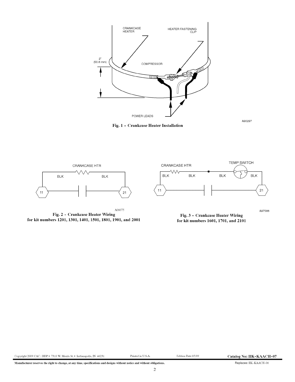
13+ crankcase heater wiring diagram
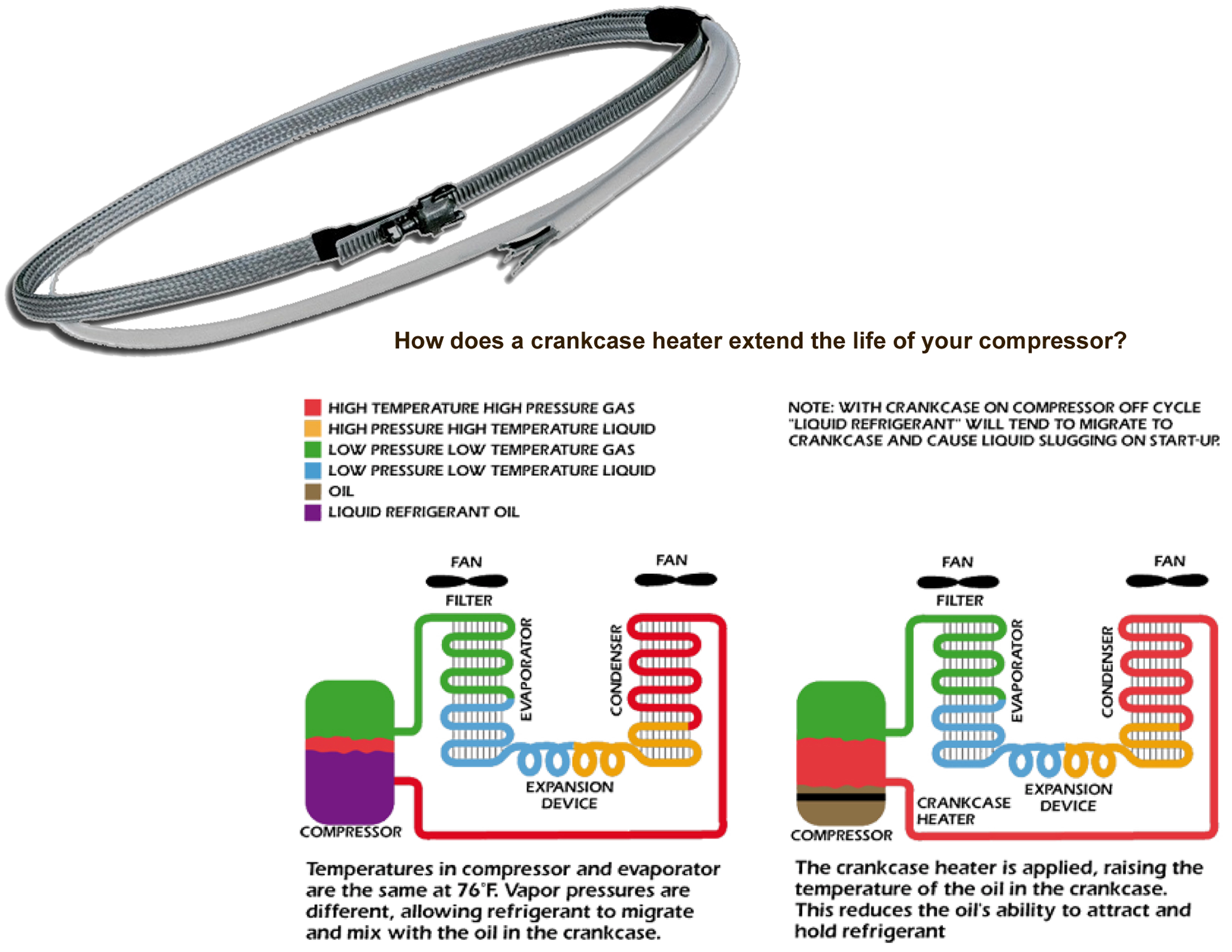
Crankcase heater 120v 100 watt. Crankcase Heater Stainer High-Pressure Switch Evaporator Bin Control Sensor Control Box Mode Switch Drain Valve.

Daikin Vrviv English Service Manual By Paulo Moreno Issuu
Fasten heater firmly in place with clip provided on heater.
. Reapply power to the. Copelands complete line of crankcase heaters offers critical compressor protection. HTR06811 - Crankcase heater 30 Watt 507 diameter 208230 Vac or HTR06851 - Crankcase heater 30 Watt 507 diameter 265 Vac and RLY01357 - DPDT relay 24 Vac coil 5060 HZ 3 A.
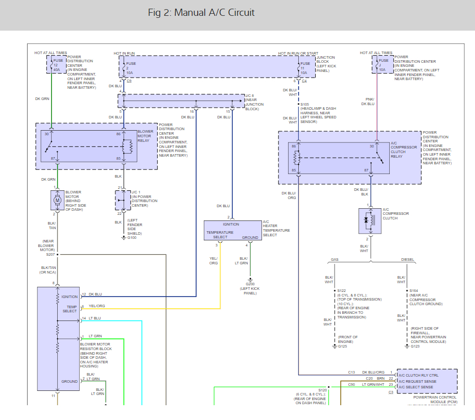
Low voltage and line voltage. 2003 Ford F 150 Vacuum Line Diagrams Online. Solenoid for reversing valve.
In case of non-communicating Indoor system disconnect factory provided wires from A B C and. Place the wiring diagram provided with the kit on the inside of the control box cover. Reinstall the side panel and the unit top and the control box cover.
Condenser and indoor fan motors. As you said it should not be wired to only be. Compressor and fan motor furnished with inherent thermal protection.
The diagram shows the cch wired to L1 and L2 making it hot all of the time. Cut quickconnect off other crankcase heater wire strip and. This is commonly done and is fine to keep it that way.
On-Board Computer IQ - Club Car. Route crankcase heater wires into control box and attach to quick--connect Route the crankcase heater wire with 14 quick--connect into control box and. HVAC Service Parts.
16 Images about How to install a RheemProtech 44-20656-82. Crankcase Heater Wiring - YouTube Figure 6-9. There are a few.
Crankcase Heater and also Carrier. Copeland crankcase heater wiring diagram. Route one crankcase heater wire into control box and attach to quickconnect line voltage terminal 11 on contactor.
Symbols are electrical representation only. Wiring Diagram WDXT2 Suction Filter S Wiring Diagram A or F opt WDAT2 CrankCase Heater AVAILABLE ACCESSORIES REPLACEMENT PARTS PartsSpecifications. CRANKCASE HEATER SWITCH COMPRESSOR NOTES.
Power Tests Always check test wire connections and devices with regard to power inside the box you are working in to stop electric shock prior to working on these people. Wiring Route one crankcase heater wire into control box and attach to quick-connect line voltage terminal 11 on contactor. Trane Heat Pump Crankcase Heater Wiring Diagram schematic and wiring.
17 Images about Figure 6-9. Wiring Piping Diagrams 19 refer to. WaterRefrigeration Circuit Diagram 1.
How to install a RheemProtech 44-20656-82.
8 Beam Hi Res Stock Photography And Images Page 30 Alamy

Research On Life Cycle Low Carbon Optimization Method Of Multi Energy Complementary Distributed Energy System A Review Sciencedirect

Crankcase Heater Systems And Methods For Variable Speed Compressors Diagram Schematic And Image 03

Wire Harness Art Of Attack Tagged 88 91 Civic Crx Ef Art Of Attack
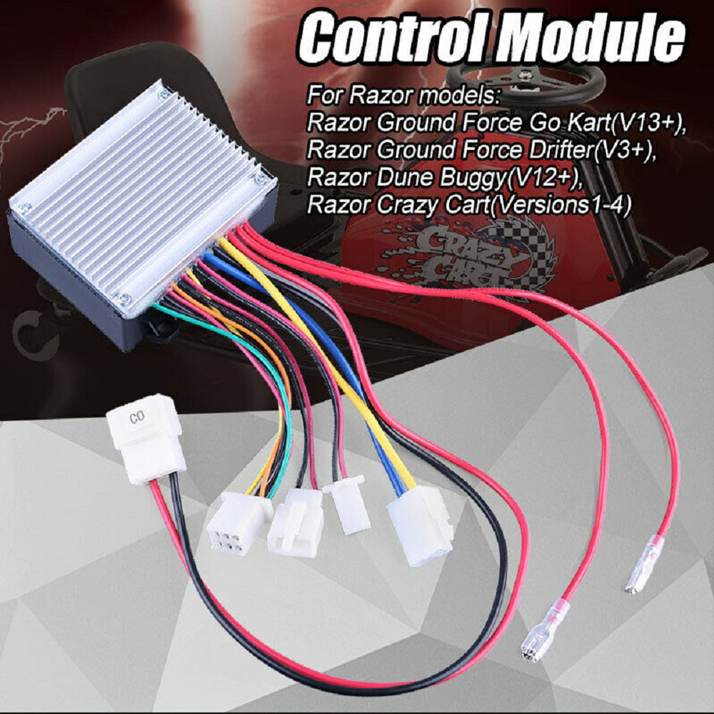
Control Module Hb2430 Tyd6k Fs Rohs 24v For Razor Ground Force Drifter V3 Walmart Com

Android Operating System Wikipedia
Further Applications And Future Potential Springerlink
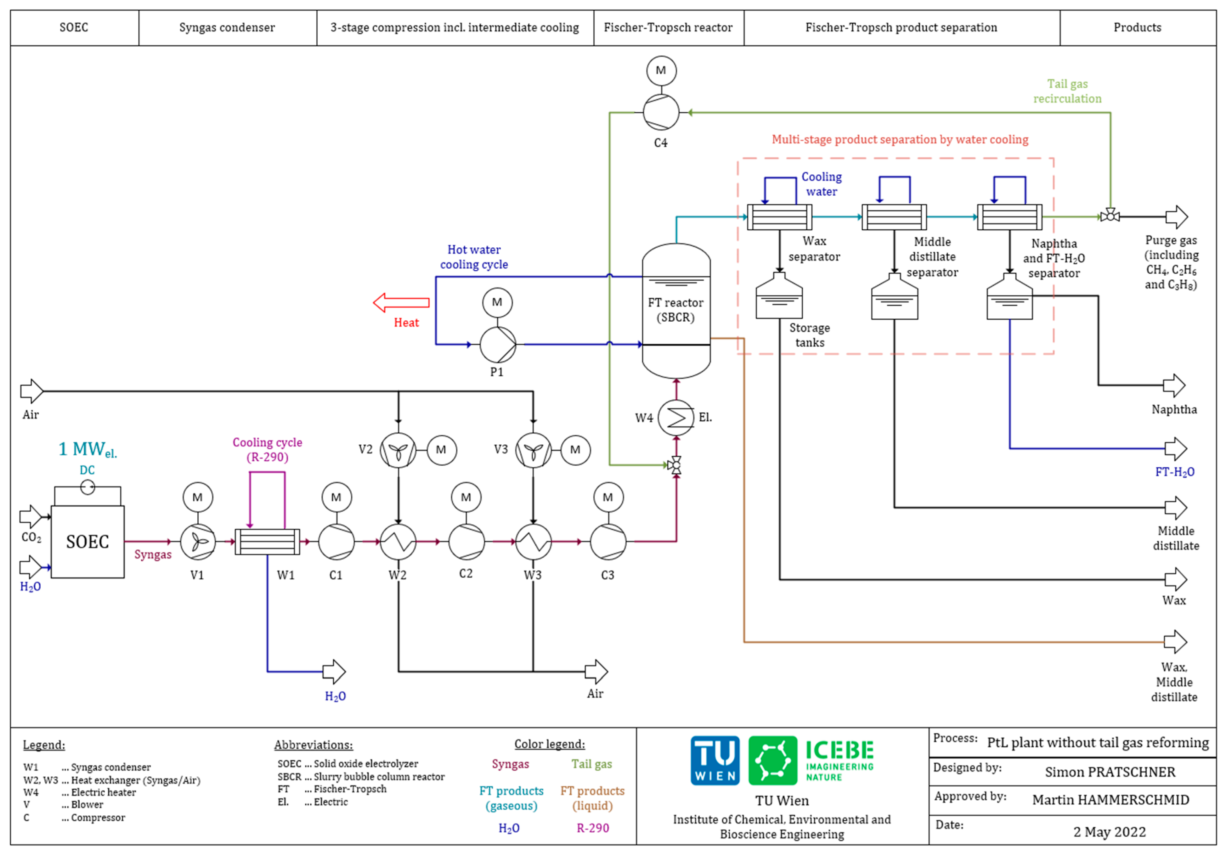
Energies Free Full Text Simulation Of A Pilot Scale Power To Liquid Plant Producing Synthetic Fuel And Wax By Combining Fischer Ndash Tropsch Synthesis And Soec Html
Carrier Controls And Hvac Accessories Manual L0907344
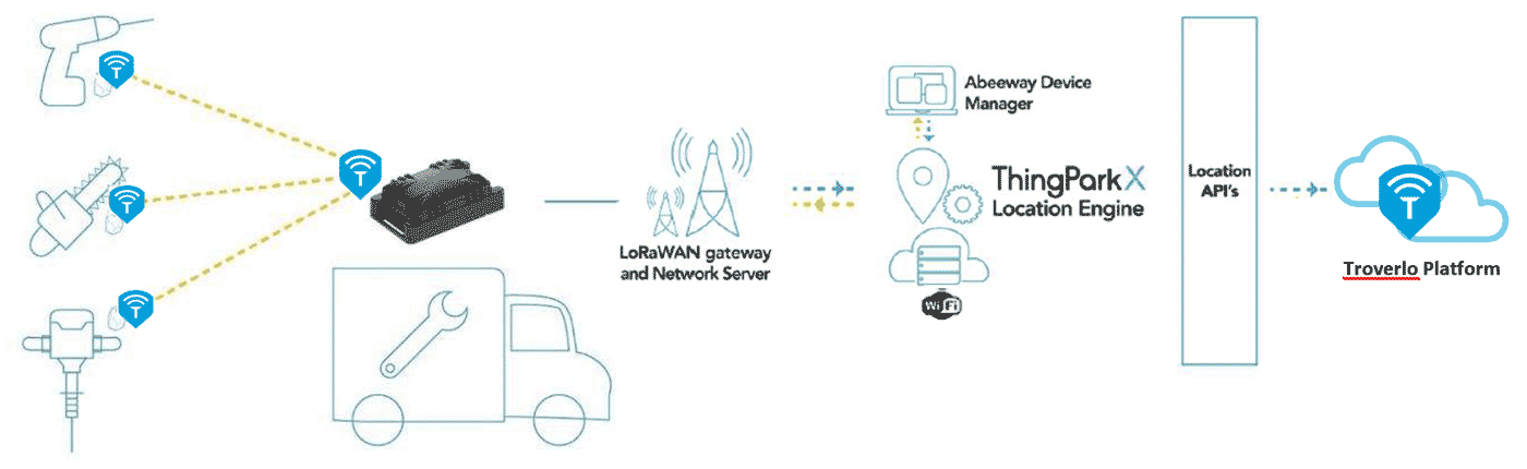
Press Release Archives Actility
Fan Blower Motor Does Not Turn On

Liebherr Pr742b Series 2 Litronic Crawler Dozer Service Repair Manual Pdf
Gpc Gph 13 Seer M Series With R 410a Goodman

Start Winding And Capacitor Crankcase Heater Youtube

Hvac Crankcase Heaters 2 Youtube
Crankcase Heater For Copeland Compressors 0263m00006 Click For Models

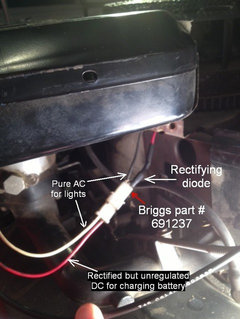
2008 Breva 750 Charging Issue